Ⅰ Summary
ZSSR-E series pneumatic O-type cutting ball valve consists of single action actuator, O-type ball valve, 2/5way solenoid valve, limit switch box and so on. The cylinder of actuator is spring to close or open. That means the valve is automatic to open or close with the spring function inner the cylinder when there is no air pressure. For considering the safe operating and protecting the valve’s quality, the single action actuator is used for the control loop in some special production link. Therefore, it is not often used for the control loop in the general link. It is received the outputting ON/OFF signals from controlling system and other control equipments. Then, the 2/5way solenoid valve is operating and switching the air channel to driving the piston in the cylinder of actuator. Therefore, the connecting rod box is operated by the piston making the traveling of the piston stem changed from linear rotation to the 0-90°angular displacement. At the same time, the stem is running that make the valve open or closed, which has finished the two ways controlling.
Ⅱ Main parameters and performance
◆Nominal pressure:
1.6Mpa;2.5Mpa;4.0Mpa
◆Working temperature:-20℃-150℃
◆Leakage: Hard seal: GB/T17213-2005Ⅳ
Soft seal: GB/T17213-2005Ⅴ
◆ Air supply pressure: 0.4Mpa~0.6Mpa
◆ Control voltage: 24VDC/220VAC
Ⅲ Ordering demands;
1. When to make the order, please choose the correct model referring to the item Ⅳ in the table. If not, you’d better provide the following information, such as the type, pressure, dimension, seal type, the main material, medium temperature, the control voltage of solenoid valve and others. The action type is formally air to open. If not, you could note it, including the special demands, such as in the anti-explosion area.
2. The choosing accessories;
Limit switches:
(1) Contacted switches (2) Induction switches (24VDC/220VAC)
The material of connecting flanges;
(1) A3(Carbon steel) (2) 304SS
Ⅳ The compiling specification of series products’ model;
| Item |
1 |
2 |
3 |
4 |
|
5 |
6 |
7 |
8 |
9 |
10 |
11 |
12 |
13 |
14 |
15 |
Explain |
| Z |
S |
|
R |
— |
|
|
|
|
|
|
|
|
|
|
|
| 1 |
Z |
|
|
|
|
|
|
|
|
|
|
|
|
|
|
|
Final controlling element symbol |
| 2 |
|
S |
|
|
|
|
|
|
|
|
|
|
|
|
|
|
Pneumatic piston actuator |
| 3 |
Cylinder installing type |
S |
|
|
|
|
|
|
|
|
|
|
|
|
|
Upright installing |
| H |
|
|
|
|
|
|
|
|
|
|
|
|
|
Horizontal installing |
| 4 |
Plug structure |
R |
— |
|
|
|
|
|
|
|
|
|
|
|
O-type |
| 5 |
Nominal pressure |
16 |
|
|
|
|
|
|
|
|
|
|
1.6Mpa |
| 25 |
|
|
|
|
|
|
|
|
|
|
2.5Mpa |
| 40 |
|
|
|
|
|
|
|
|
|
|
4.0Mpa |
| 6 |
Control type |
E |
|
|
|
|
|
|
|
|
|
Cutting type |
| 7 |
Cylinder action type |
S |
|
|
|
|
|
|
|
|
Single action cylinder |
| 8 |
Action type
|
B |
|
|
|
|
|
|
|
Air to close |
| K |
|
|
|
|
|
|
|
Air to open |
| 9 |
Valve’s state with failure action
|
O |
|
|
|
|
|
|
Open fully |
| C |
|
|
|
|
|
|
Close fully |
| 10 |
Nominal diameter DN(mm)
|
15 至200 |
|
|
|
|
|
15、20、25、32、40、50、65、80、100、125、150、200 |
| |
|
|
|
|
| |
|
|
|
|
| 11 |
Seat type
|
Y |
|
|
|
|
Hard seat |
| R |
|
|
|
|
Teflon soft seat |
| 12 |
Valve body material
|
P |
|
|
|
CF8 |
| M |
|
|
|
CF 8M |
| L |
|
|
|
CF 3M |
| 13 |
Input signal range
|
D3 |
|
|
220VAC |
| D4 |
|
|
24VDC |
| 14 |
Position limit switch
|
A |
|
Contacted switch |
| B |
|
Induction switches(24VDC) |
| C |
|
Induction switches(220VAC) |
| 15 |
Name of manufacture
|
LP |
Zhejiang Tongpu automatic control equipment CO., LTD. (Wenzhou Lipu automatic control equipment CO., LTD.) |
Ⅴ Safety
ⅰWe make sure all the valves is very safe only if the material and pressure accord with the requirements in your order.
ⅱAccording to the 4th part in the national standard(GB/T17213-2005/IEC60534-1999) of control valves industry area, it is the examination and testing on duty. We have test and examined the pressure and material following the testing report so that we are sure the safety of valves. The technical demands as followed,
1. Material testing
The physical test and chemical composition of the material for producing control valves accord with the standard of control valve or the concerned requirements in the order.
2. the static pressure testing in the liquid
All the compositions of control valve, even no actuator, which must be finished the static testing in the liquid according to the concerned pressure. i.e. it is tested by 1.5 times to the rating pressure.
Ⅵ Principle of operation
The O-type cutting ball valve is made up of pneumatic actuator, valve body, solenoid valve, air filter, air channel components, connecting and fastening pieces and so on. It finishes the position controlling from full open to full close by the solenoid valve. Then, the signal (e.g., 24VDC, 220VAC) from the controlling instrument or manual tool operating will control the solenoid valve, which output the signal of air pressure at once to impulse the actuator so that it finishes the position controlling from open to closed by the wheel box to drive the O-type valve trim.
Ⅶ Installing, usage and maintenance
◆ The position of installing the ball valve would be in the place as standing by the building platform 、a walking block ect. in order to having the best watching、adjusting、Operating、maintenance and repairing.
◆The pneumatic O- type ball valve may horizontal fix or vertical installing.
◆When to install the valve body, the medium must be flow to in a direction from the arrows on the valve body.
◆You would be added to lube oil in the wheel box of the actuator and the joints for half year at least.
◆The waste materials should be removed before installation of piping systems. Once installed, the position of the valve body must be opened completely to sweep by blowing the wind into a pipeline.
◆There are two screws(M12 ~ M20) on the upper end of the cylinder of the pneumatic actuator and the lower end of the box, which is used for adjusting the position from fully open to fully close.
Ⅷ Storage
Control valve had better be kept in the room among 5℃-40℃ temp. and ≤90% in the humidity. You’d better make sure there are no corrosive characteristics and other bad components in the air.
Ⅸ Packing and transportation
The packing material must accord with the concerned packing standard and demands. The packing must be intact and whole. It should have the own symbol against rain or dust and how to lay up. You should prevent the strong shaking in order to protecting the packing well in the journey of transportation.
X、ZSSR-E pneumatic cutting ball valve (double acting)
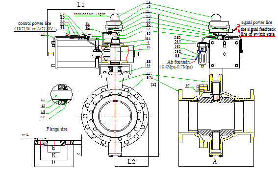
1A.Position of valve show cover 1B.Switch box cap 1C.Switch box connection joint 1D.coreend plate 1E.Switch box retroact shift 4.Box
26.Axle 35B.Air filter nut
35C.Air filter framer 5D.Air filter core 35E.Air filter over coat 45.Piston rod 48.Piston rod gallow sheath 49.Piston rod seal ring 50.Cylinder gallow lid circle nut 51.Switch box and bolt 52.Spring washer 53.Box lid screw 54.Washer
55.Frame bolt 56.Frame bolt spring washer 57.Body with flange 57A.Body cap 58.Into air joint 59.Air pipe
60.Solenold valve 61.Solenold valve fix end plate 62.Solenold valve fix screw 63.Solenold valve guilder 64.Solenold valve coil 65 Solenold valve connection joint 66.Solenold valve signal line 67.Body and cap seal cushion
|
Nominal
Size
Dn
|
Flow
Quotiety
(kv)
|
Dimension
|
Flange:gb/t9119-2000
|
|
A
|
L
|
H
|
X
|
Valve
N·W
(Kgs)
|
D
|
C
|
K
|
E
|
n-1
|
Flange
N·W
(kgs)
|
|
Series1
|
Serie2
|
|
20
|
38
|
140
|
310
|
450
|
50
|
12.55
|
105
|
16
|
75
|
27.5
|
26
|
4-14
|
0.85
|
|
25
|
72
|
145
|
310
|
465
|
50
|
13.60
|
115
|
16
|
85
|
34.5
|
33
|
4-14
|
0.96
|
|
32
|
110
|
165
|
390
|
505
|
80
|
19.00
|
140
|
18
|
100
|
43.5
|
39
|
4-18
|
1.59
|
|
40
|
170
|
171
|
390
|
520
|
80
|
21.70
|
150
|
18
|
110
|
49.5
|
46
|
4-18
|
1.82
|
|
50
|
270
|
214
|
390
|
550
|
80
|
26.30
|
165
|
20
|
125
|
61.5
|
59
|
4-18
|
2.43
|
|
65
|
406
|
232
|
390
|
575
|
80
|
29.95
|
185
|
20
|
145
|
77.5
|
78
|
4-18
|
2.97
|
|
80
|
510
|
202
|
420
|
580
|
100
|
37.45
|
200
|
20
|
160
|
90.5
|
91
|
8-18
|
3.23
|
|
100
|
940
|
232
|
420
|
605
|
100
|
40.75
|
220
|
22
|
180
|
116
|
110
|
8-18
|
4.52
|
|
125
|
1400
|
242
|
490
|
660
|
125
|
50.45
|
250
|
22
|
210
|
141.5
|
135
|
8-18
|
4.93
|
|
150
|
2200
|
297
|
490
|
710
|
125
|
65.35
|
285
|
24
|
240
|
170.5
|
161
|
8-22
|
6.53
|
|
200
|
3500
|
365
|
580
|
830
|
125
|
94.50
|
340
|
26
|
295
|
221.5
|
222
|
12-22
|
9.01
|
|
250
|
5000
|
400
|
610
|
940
|
160
|
163.20
|
405
|
28
|
355
|
276.5
|
276
|
12-26
|
13.2
|
|
300
|
7600
|
496
|
610
|
1130
|
200
|
266
|
460
|
32
|
410
|
327.5
|
328
|
12-26
|
17.34
|
|
350
|
12500
|
608
|
610
|
1180
|
200
|
409.15
|
520
|
35
|
470
|
359.5
|
380
|
16-26
|
26.33
|
|
400
|
17500
|
610
|
650
|
1390
|
260
|
575
|
580
|
38
|
525
|
411
|
430
|
16-30
|
33.59
|
|
450
|
21650
|
660
|
650
|
1430
|
260
|
810
|
640
|
42
|
585
|
462
|
484
|
20-30
|
43.86
|
|
500
|
25800
|
700
|
650
|
`1510
|
260
|
1000
|
715
|
46
|
650
|
513.5
|
534
|
20-33
|
61.07
|
|